Common Challenges Relative to the use of a Decanter Centrifuge for Barite Recovery in the Oil & Gas Industry
When decanter centrifuge is properly deployed, they can have dramatic effects on drilling performance. In fact, without them, many of the advances made in drilling would not have been considered achievable. Classically, we believe that centrifuges can achieve two common goals:
- Reduce the content of drilled fines, specifically colloidal solids, and
- Perform barite recovery in order to reduce drilling fluid additive costs.
Respectfully, each goal presents a valiant initiative. However, when combined they also present a number of complications that are typically overlooked by most modern solids control service providers.
In understanding these complications, it is important to recognize that the ultimate goal of a decanter centrifuge is to reduce the plastic viscosity of the drilling fluid. This improves the drilling rates of penetration and reduces the damaging effects of accelerated wear on bits, mud pumps, and related equipment. Further, if all goes as planned, by controlling the colloidal solids, significantly less mud make-up dilution is required. In essence, when properly used, a decanter centrifuge should enhance the drilling fluid properties, thereby improving rig performance (i.e. increased rates of penetration, improved cake wall stability, reduced bit torque and reduce pipe drag). Concurrent to these benefits, a decanter centrifuge can also be used to lower waste disposal costs by reducing the volume of waste drilling fluid and reduce raw material additive costs by maintaining the target properties of the drilling fluid. Generally speaking, this is the canned sales pitch offered to drill rig operators, used by solids control service companies, in order to market barite recovery and solids control services.
Despite these goals, the evolution of the drilling industry over the last few years has resulted in the rapid deployment of decanter centrifuges that are unable to achieve the results targeted or marketed. Though the centrifuges available in the market have indeed improved, modern drilling practices have evolved greatly in the last decade. Modern drilling rigs are continuing to set new standards by drilling deeper, faster, and longer (relative to the pervasive utilization of directional drilling techniques). Given the recent evolution of drilling, there are indeed concerns growing as to whether or not the application of a decanter centrifuge has evolved at an equal pace. In fact, it was almost 10 years ago when concern was initially raised by Eugene E. Bouse in his May 4th, 2013 E&P Magazine article entitled “The Use and Misuse of Centrifuges”. As noted by Mr. Bouse, “Unfortunately, misuse has become more common, and many of the costly present-day practices are so ill-conceived that they are actually detrimental to both mud quality and waste minimization efforts.” As will be carefully consider through the remainder of this document, Mr. Bouse was pointing to several concerns relative to barite recovery services.
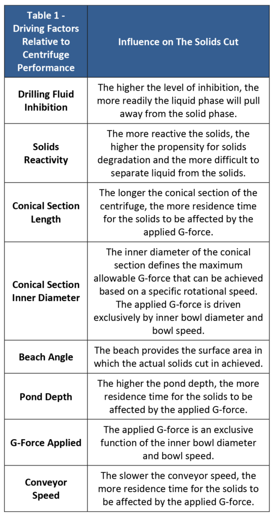
A decanter centrifuge is deployed in order to “cut” solids from the liquid stream; essentially creating two separate streams from the incoming influent. We typically consider the cut to be the “underflow” (a.k.a. “solids discharge”, “cake”, and/or “heavy phase effluent”) and the cleaned liquid stream (a.k.a. “centrate” or “light phase effluent”) to be the “overflow”. The centrate will contain most of the liquid and the finer solids. The cake will contain less liquid and the coarser solids. The goal is to have the cake as dry as possible with the lowest volume of surface wetting liquid achievable. The ability to achieve this goal is a direct function of the drilling fluid inhibition, formation solids reactivity (defined as the combined measure of the potential for a material to cause a negative impact to the drilling activities by material hydration and/or dispersion), decanter centrifuge design parameters (i.e. conical section length, conical section inner diameter and beach configuration), and decanter centrifuge operating parameters (i.e. pond depth, g-force applied and conveyor speed). However, it is important to note that the goal of achieving a “dry” solids discharge should not precede the goal of achieving the proper colloidal solids cut. Table 1 highlights the physical effect each of these parameters has on the ability of the decanter centrifuge to make a cut.
The application of “Traditional Centrifuging” techniques removes both the ultrafine and colloidal solids regardless of their classification as formation solids (a.k.a. drilled solids, low gravity solids or LGS), or drilling fluid solids (a.k.a. weighting agents – most commonly barite). The goal would be to remove all suspended solids above a targeted particle size distribution, whereby new drilling fluid solids would be added to the system. Relative to Barite Recovery, the traditional intent is to maintain the larger solids, specifically barite and those solids classified by API as fine and ultra-fine (assuming that most medium, intermediate and coarse solids were appropriately removed by the primary solids control systems; the flow line shakers) for return to the drilling fluid.
As highlighted by Figure 1 and Figure 2, ultra fine and fine solids fall within the American Petroleum Institute’s (“API”) standard particle size distribution classification of barite.
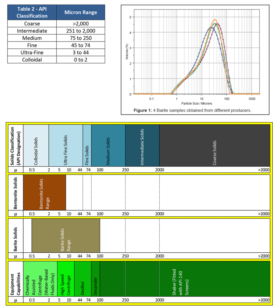
Figure 2: Comparative Particle Size Distributions of Bentonite and Barite Relative to API Defined Particle Size Distributions and General Solid Control Equipment Capabilities
Section 2.0 - Defining Traditional Barite Recovery With A Decanter Centrifuge
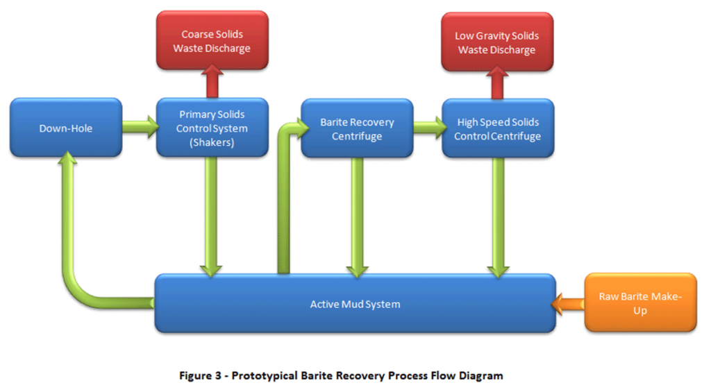
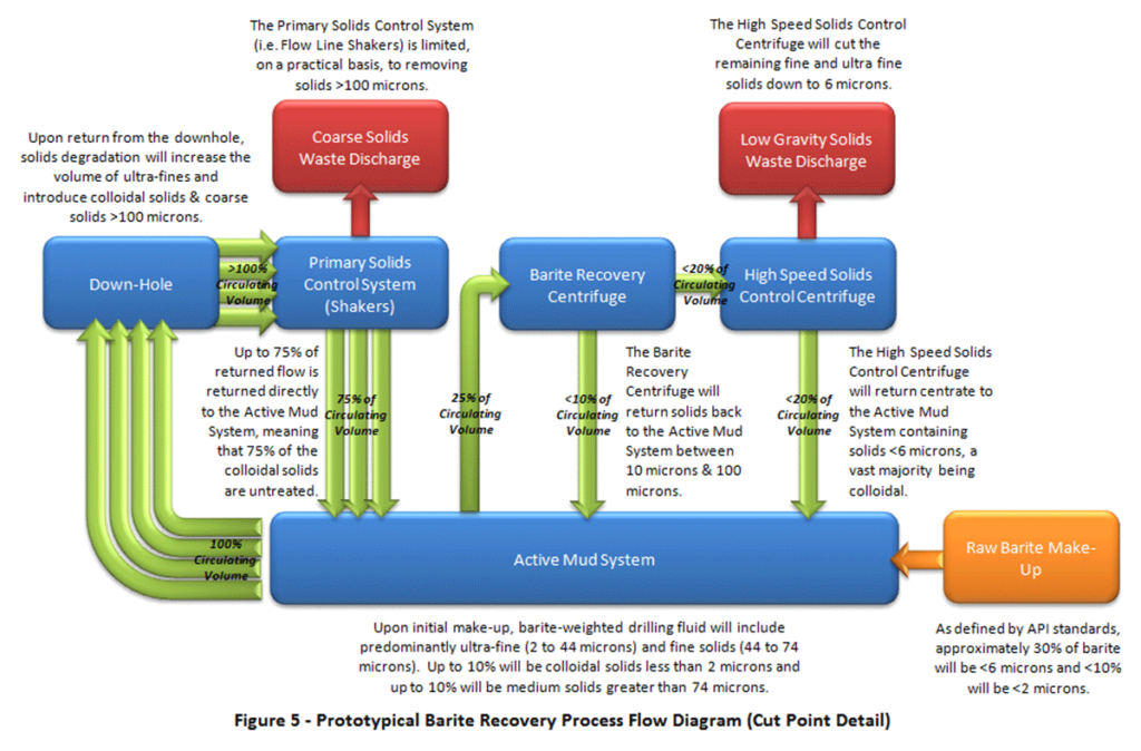
For “Barite Recovery” operations, service providers pair two centrifuges together, in which the first decanter centrifuge targets solids between a 10 and 100μm range and the second and the second purportedly removes those solids less than 10μm. This 10 and 100μm range is the sweet spot within the particle size distribution curve for barite as highlighted in Figure 1. The lower end of this range (10μm) is set by the centrifuge’s applied G-force, where the upper end of this range (100μm) is set by the practical suspended solids cut achieved by the primary solids control system, the flow line shakers. The influent to the barite recovery centrifuge comes as a “slip-stream” from the active mud system. This means that the full circulation volume of the Active Mud System is not sent through the centrifuge system. The first centrifuge’s solids “cake” is returned to the Active Mud System with the goal of recycling barite, where the centrate (containing the colloidal and ultrafine solids) is plumbed to the second centrifuge.
The second decanter centrifuge is configured as a high speed centrifuge to remove low gravity solids. The target range rests between the maximum capability of the centrifuge, relative to the maximum achievable G-force that can be applied (typically 2 to 5μm), and the lower range defined by the barite recovery centrifuge. The solids “cake” is considered waste and is disposed of, whereas the “cleaned” centrate is returned to the Active Mud System. Figure 3 provides an illustration of the prototypical Barite Recovery Process using a decanter centrifuge:
Section 3.0 - Colloidal Solids and Their Effect on Plastic Viscosity
Understanding colloidal solids, especially as it relates to modern oil & gas solids control practices, is not easy task. Most decanter centrifuge operators do not understand that drilling fluids performance and the associated plastic viscosity are driven by the colloidal solids content, not “low gravity solids”. Even fewer operators understand the different between low-gravity solids and colloidal solids. However, when comparing them to every day rig terms, it can be easier to digest.
As highlighted in Figures 1 and 2, barite has a particle size distribution that ranges from 1 micron to 100 microns (predominantly ultra-fine and fine solids). API specifies that barite should achieve a size distribution where the percentage of material >75μm is minimized, while ensuring that the percentage of material <6μm is no higher than 30% by weight.
As for bentonite, the particle size distribution can range from under 1μm up to 10μm (colloidal and smaller ultrafine solids). As highlighted by Figure 2, bentonite solids have a much smaller particle size distribution in comparison to barite and hence the reason that bentonite is typically considered a “thickening agent” to increase viscosity, whereas barite is simply considered a weighting agent. Barite has only a modest impact on viscosity, as the aggregate surface area of the solids are dramatically lower than the surface area exhibited by the solids found in bentonite. This comes from the fact that the negative effects of elevated plastic viscosity are predominantly driven by the available surface area exposed by colloidal solids, which are highly prevalent in bentonite, in comparison to barite.
Despite the fact that the particle size distribution bands are fairly well defined, measuring solids within these ranges is complicated. The common mistake made by centrifuge operators is the reliance on a “retort” analysis. Though the retort is a practical tool to measure the total aggregate mud weight, it is useless for defining the change in plastic viscosity (i.e. increase in total surface solids surface area as it directly relates to an increase in the colloidal solids content) associated by the continued and natural degradation of drilling fluid and formation solids into colloidal solids. To meaningfully pinpoint the changing conditions (a.k.a. rheology) of the drilling fluids through the well cycle, details relative to the particle size distribution must be captured. Only a particle size distribution analysis can shed light on the total surface area exhibited by the drilling fluid suspended solids. As this test is not traditionally considered practical or “cost-effective” to complete on the rig site on a daily basis, most operators ignore it, in lieu of the more commonly adopted retort analysis.
Unfortunately, by relying on the retort analysis exclusively, centrifuge operators and mud engineers are unable to ascertain the characteristic life cycle of the colloidal solids. Many mud engineers will simply assume that when the mud weight increases, as defined by the retort analysis, the only logical option is to increase the treatment capacity of the centrifuges or increase the applied G-force. However, given the fact that the centrifuges are only treating a small percentage of the total circulating volume and that centrifuges are unable to manage colloidal solids, operators are left fighting a losing battle.
Section 4.0 – The Heart of Common Solids Control Failures
As noted in Section 1.0 and Section 2.0, drilling fluid conditions will inevitably degrade over the course of the well. Theoretically, there are means to keep this from happening. However today’s modern solids control techniques, specifically those involved in traditional barite recovery operations, make this impossible to avoid. This is driven by two common Drill Rig Operator and Solids Control Service Provider errors:
- Coarse Flow Line Shaker Screens – Most drilling rigs operate their primary flow line shakers with screens far too coarse (Screens rated at API 120 or lower) to achieve meaningful solids control. This is driven predominantly by a multitude of factors that are now caught up in a viscous industrial cycle. In order to cut costs, drilling rig operators use coarse screens that last longer and require significantly less personnel attention. Further, coarse screens minimize the risks of whole mud losses when drilling fluid circulation rates are high. However, the risk of whole mud losses would be significantly reduced, if a sufficient number of shakers (i.e. sufficient surface area) were installed. With all this said, the use of coarser screens on the flow line shakers simply supports the business models of drilling fluid additive providers and solids control service providers. By using coarse screens, drilling rig operators have become more reliant on solids control service companies to maintain the drilling fluid performance and ultimately the rig’s rate of penetration. Oddly enough, most drilling rig hands do not understand that in most cases, the “wetter” the solids discharge from the flow line shakers, the higher quality solids cut is being achieved. This is especially the case when drilling through reactive hydrophilic soils.
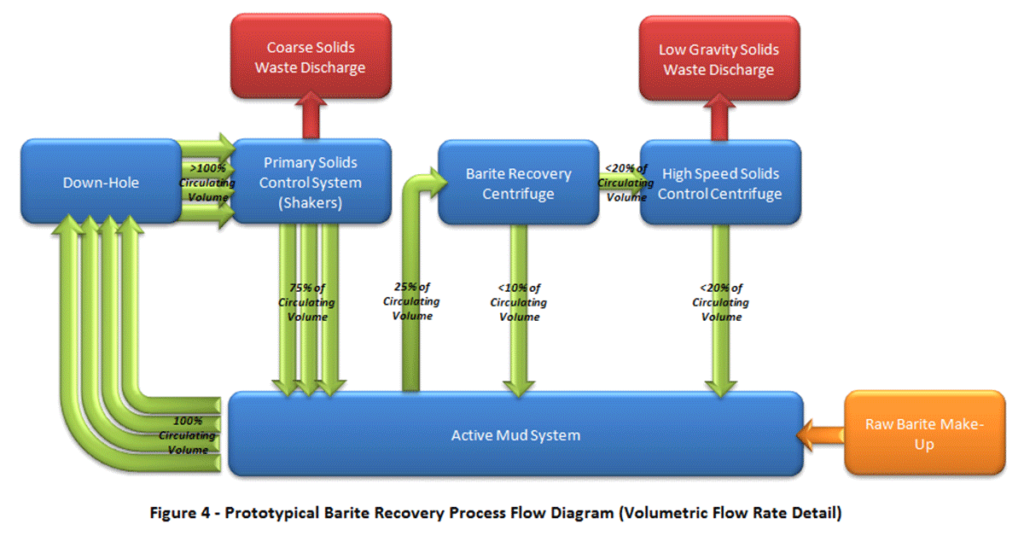
- 25% Centrifuge Slip Stream Treatment – The application of centrifuges continues to target a 25% slip stream (i.e. a minority of the circulation rate is routed to the centrifuge treatment systems). Despite the fact that most rig drilling fluid circulation rates will operate between 800 and 1,500 gallons per minute, the largest centrifuge applications treat 100 to 300 gallons per minute. The general impression, as illustrated by Figure 3, is that a constant stream of fluid is being cleaned from the active system, therefore constantly removing colloidal solids. Unfortunately, most centrifuge applications fail to treat the full circulating volume. As highlighted by Figure 4, most centrifuge applications treat only one out of four parts of the drilling fluid during each pass. The challenge is that modern drilling techniques constantly generate colloidal and ultrafine solids, through the natural degradation cycle, faster than can be removed by the solids control system. Ultimately, during each cycle of the drilling fluids, those three out of four parts not treated by the centrifuges, will simply further degrade and be joined by more colloidal solids from the drilling process. If only one out of four parts of the further-degraded drilling fluid stream is treated during the next pass, the centrifuge systems will struggle to remove the low gravity solids being generated. How long would it take for your boat to sink if it was taking on water at a rate of four buckets a minute and you only have the ability to dump one bucket a minute?
The combination of the above factors results in modern drilling rigs operating with primary flow line shakers that are far too coarse to sufficiently support the goals of the solids control program and utilizing insufficient centrifuge capacity to make up for the poor performance of the shaker systems. Regardless of our desires, the suspended solids found in drilling fluids, as noted by Mr. Bouse, “are subjected to conditions that cause a progressive reduction in particle size, with a corresponding increase in surface area. This has serious adverse effects on mud quality even though solids content remains constant.” Even though the mud weight may stay the same, as the drilling fluid ages, the surface area inevitably rises. In fact, it is possible to have a drop in the mud weight, but still have an increase in the plastic viscosity as a direct result of elevated levels of colloidal solids.
Section 5.0 – The Heart of Common Barite Recovery Failures
For years, the traditional economic justification for using centrifuges with weighted drilling fluids has been based on the savings realized by barite recovery. The assumption is that recycling barite will save money. However, it is more important to understand that when centrifuges are not deployed, the concentration of ultrafines and colloidal particles rise at a much faster rate. As we have previously noted, this inevitably leads to high plastic viscosity, which leads to poor drilling fluid quality, which leads to a myriad of down-hole issues. One stuck pipe, can cost the drilling rig operator much more than the total cost of the drilling fluids being used on the well. The fact is controlling colloidal solids provides a much higher value than attempting to lower raw barite costs.
As discussed in Section 1, in a Barite Recovery System the first centrifuge operates under the practice of “traditional centrifuging”, whereby the underflow (a.k.a. “solids discharge”, “cake”, “heavy phase effluent”) is returned to the active mud system in order to recover barite. The overflow (a.k.a. “centrate” or “light phase effluent”), containing the vast majority of the colloidal solids and ultrafines, is then diverted to the high-speed solids control centrifuge. Instead of discarding the ultra-fine and colloidal solids feedstock to the entire drilling fluid system, it is submitted for supposed “treatment”, whereby only clean, “colloidal-free” drilling fluid is returned to the active drilling fluid system.
The fallacy of this practice is better understood when considering that centrifuges do not efficiently cut suspended solids from the drilling fluid stream less than 5μm. Though centrifuges capable of achieving 2,400 G can indeed theoretically cut solids down to 2μm, the effectiveness of making that cut are dictated by the formation solids reactivity, level of drilling fluid inhibition, and the general make-up of the drilling fluid. In fact, depending on the suspended solids properties and level of drilling fluid inhibition, achieving a 5 micron cut may require significantly more than 2,500 G’s of energy.
The barite recovery concept is fundamentally flawed, as a result of two erroneous assumptions:
- The first centrifuge is capable of intelligently separating barite from low gravity solids; and
- The second centrifuge is capable of producing a colloidal, solids-free liquid for return to the drilling fluid.
As noted by Mr. Bouse, “both of these assumptions are incorrect and ignore the physics of sedimentation.” More important to these two erroneous assumptions, is the assumption that the deployment of centrifuges, in weighted drilling fluid applications, has the objective of removing low gravity solids. This is not the goal. The goal is to remove colloidal and near-colloidal from the drilling fluid, as soon as absolutely possible.
As noted by Mr. Bouse, “Using the “quick and dirty” barite recovery concept to justify centrifuge rental is a simple, though flawed, calculation that has impeded the understanding of the real benefits of using centrifuges with drilling fluids.” The fact is that most modern centrifuge deployments are not only unproductive, they are counterproductive. This predominantly driven by the fact that most centrifuge operators do not understand the life cycle of colloidal solids or how the systems they are operate interact with those colloidal solids. As noted by Mr. Bouse, the most common form of centrifuge misuse is “the practice of running two centrifuges in series to “recover the barite” with the first and “discard the drilled solids” with the second.”
The fact is that the colloidal and near colloidal solids are the predominant influence on a drilling fluid’s plastic viscosity and are so small that their specific gravity is “barely relevant”. This concept is explored in more detail in the next section.
Section 6.0 – Understanding the Limits of Barite Recovery Relative to Colloids
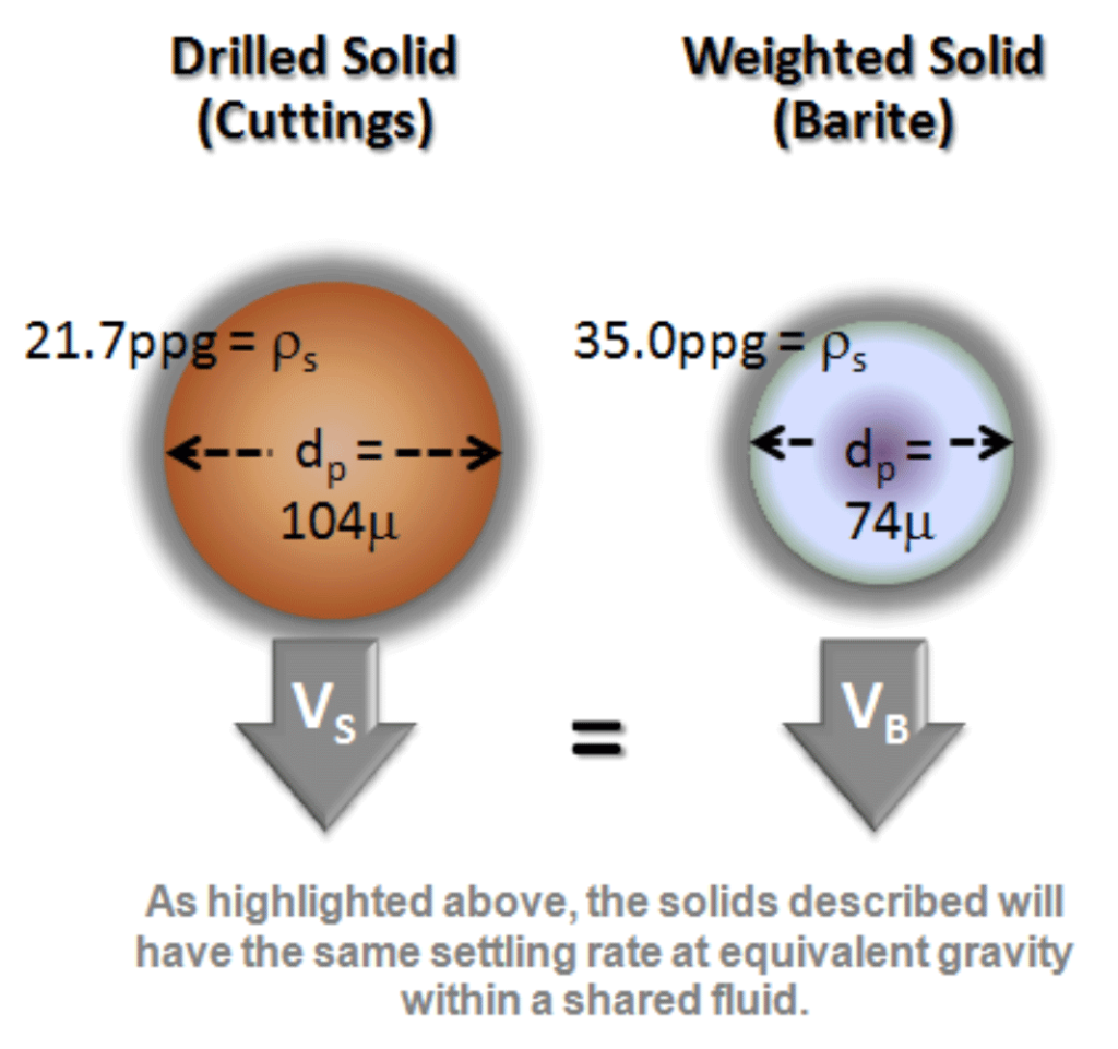
Centrifugation is accelerated sedimentation using increased gravitational forces and is described by Stokes’ Law. As noted by the formula below, it states that the sedimentation rate is directly proportional to the difference in density between the settling particle and the surrounding liquid, and inversely proportional to the viscosity of the liquid.
As drilling fluids age, they contain both formation solids and drilled fluid solids that range from <1μm to more than 100μm (depending on the quality of the primary solids control achieved by the shakers). Assuming that the average specific gravity of barite and low-gravity solids particles are 4.2 and 2.6, respectively, the mass of a barite particle is equal to that of an LGS particle about 50% larger. For example, if most of the barite particles <6μm remain in the overflow, then most of the low-gravity solids particles <9μm will also remain in the overflow. The larger particles, both barite and formation solids, will be found in the underflow. Thus, we don’t separate barite from low-gravity solids; we separate heavier (larger) particles from lighter (smaller) ones.
Let’s consider what happens in the typical dual centrifuge barite recovery system. Assuming that the “barite recovery” unit makes an 10μm cut on barite, and that the second “high speed unit” makes a 5μm cut, most of the barite larger than 10μm and the low gravity solids larger than 15μm are returned to the mud at the first stage. At the second stage, the remaining barite larger than >5μm and the low-gravity solids >7.5μm are discarded, and the finest, most damaging, material is returned to the drilling fluid.
As is highlighted by Figure 5, no matter what the two cut points are, the material that is removed from the active mud system falls between them (approximately 5 to 10μm). This fraction includes barite in a perfectly acceptable size range and low-gravity solids that are too large to increase plastic viscosity, and too fine to be very abrasive. All of the finest solids, both degraded barite and cuttings in the colloidal and ultra-fine range, are returned to the mud system, assuring a progressive degradation in average particle size and in mud quality. The decreasing particle size increases the viscosity and the need for barite and solute dilution, while diminishing wall cake quality and promoting the deterioration of hole conditions.
It is also important to recognize that with viscous oil-based and synthetic drilling fluids, solids that behave like colloids can be much larger (10 to 15μm). Their concentration must be controlled by dilution or by traditional centrifuging where the colloidal solids-laden centrate is discarded.
Based on the details presented above, despite the addition of new barite and solute dilution, traditional barite recovery systems do not remove the solids directly affecting plastic viscosity. The mud engineer can continue to add new barite, but this does not change the volume of colloidal solids re-circulating through the system. The only way to reduce the colloidal solids content is to continuously purge the aged drilling fluid versus introducing it to the second high-speed solids control centrifuge for further “cleaning”.
Worse yet, the desirably sized barite that is discarded by the high-speed solids control centrifuge must be replaced by fresh barite, 30% of which can be particles finer than 6 μm, and 10% of which can be expected to be colloidal (< 2 μm). This further reduces average particle size and accelerates the decline of drilling fluid quality. This means that for every 10 pounds of new barite that are introduced, almost 3 pounds of this material will pass through both centrifuges and build up in the drilling fluid causing an inevitable rise in colloidal solids content and plastic viscosity. This is independent of the degradation effects that the solids will undergo throughout their well life cycle.
The return of centrifuge overflow (a.k.a. “centrate” or “light phase effluent”) to the mud system always involves the return of colloids; thus, this practice will always result in a progressive degradation of the suspended solids. As such, operators will commonly experience the need to increase the volume of drilling fluid being treated and exert higher amount of energy, in the form of G-force, in order to keep up with the drilling fluid condition.
The two-stage centrifugation process is expensive and, if not properly understood, can be harmful. By increasing the need for dilution, it increases mud cost and drilling waste volume. Even worse, it naturally reduces mud quality. The industry is currently led to believe that by running centrifuges in series we are “recovering the barite at the first stage, and discarding the drilled colloidal solids at the second.”

Section 7.0 – Decanter Centrifuge Challenges Conclusion
While most believe the liquid phase is too costly to discard and that any solids removal is value-added to the drilling contractor, remember that the problem solids are the finest particles. Adverse plastic viscosity and drilling fluid performance is the direct result of colloidal solids, not low gravity solids. Discarding the desirable solids needed to maintain the mud weight, while retaining the finest particles, does not alleviate the problem; it exacerbates it. Traditional centrifuging is preferred, but is hard to swallow when it requires the continual discarding of centrate. This may not be necessary when the fluid is not used long enough for the colloidal concentration to increase to problem levels. However, when colloids do present problems, traditional centrifuging is the best way to restore mud quality.
Ultimately, the objective of centrifuging weighted drilling fluids is the removal of colloidal and near-colloidal particles, not the removal of low-gravity solids. Colloids are particles that are so fine that they will not settle in pure water; therefore, regardless of the intent or energy used, they cannot be separated by centrifuging. The punch-line is simply, colloidal-rich centrate cannot be “cleaned” with centrifuges alone. Worse yet, there is no practical field method to remove colloids from oil-based drilling fluids in which they are suspended.
Elgin Separation Solutions is a turn-key solutions company in the Oil & Gas, Mining, Trenchless and Water Intake Industry. Contact us today to learn more about Elgin.
To download this white paper ‘Click Here’
Read more about decanter centrifuge operation ‘Click Here’

